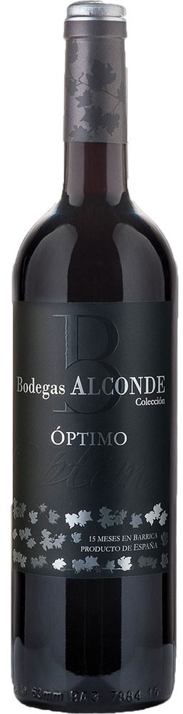
Bodegas Alconde Coleccion Optimo Crianza Tinto de...
8,95 €
Klauss Getränkeshop
ab 5,90 € Versandkosten
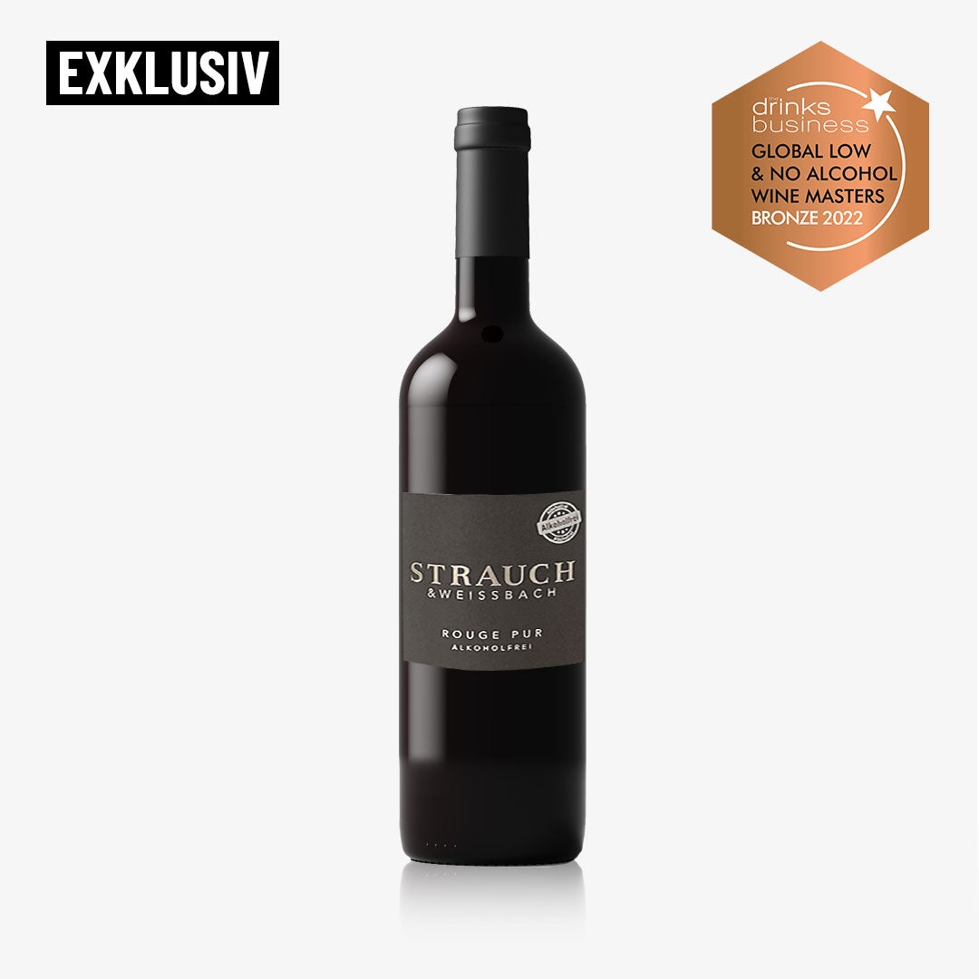
ROUGE PUR BIO: Alkoholfreier Rotwein aus der Strau...
13,50 €
alkoholfrei-vom-winzer.de
ab 6,99 € Versandkosten
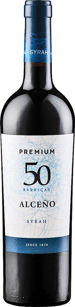
12er Set Alceno Syrah Premium 50 Barricas 2021 - V...
9,49 €
VinoMi
Versandkostenfrei

Primitivo di Manduria Primitivo di Manduria DOP 20...
17,80 €
Delinat - Wein aus gesunder Natur
ab 3,60 € Versandkosten
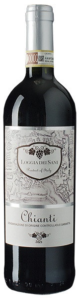
Chianti Loggia Dei Sani Rotwein trocken 0,75 l
5,49 €
Schneekloth Weindepot
ab 6,50 € Versandkosten
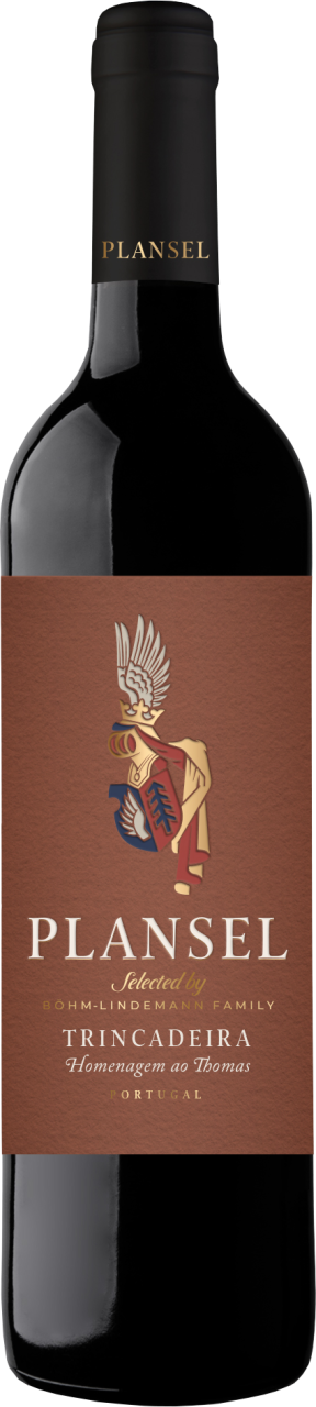
Plansel Selecta, Homenagem ao Thomas Tinto 2021
9,95 €
walterdeitermann.de
ab 6,95 € Versandkosten
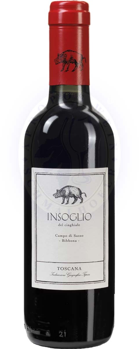
Insoglio Del Cinghiale Igt 2022 0,375l
14,69 €
AproposWein
ab 4,95 € Versandkosten
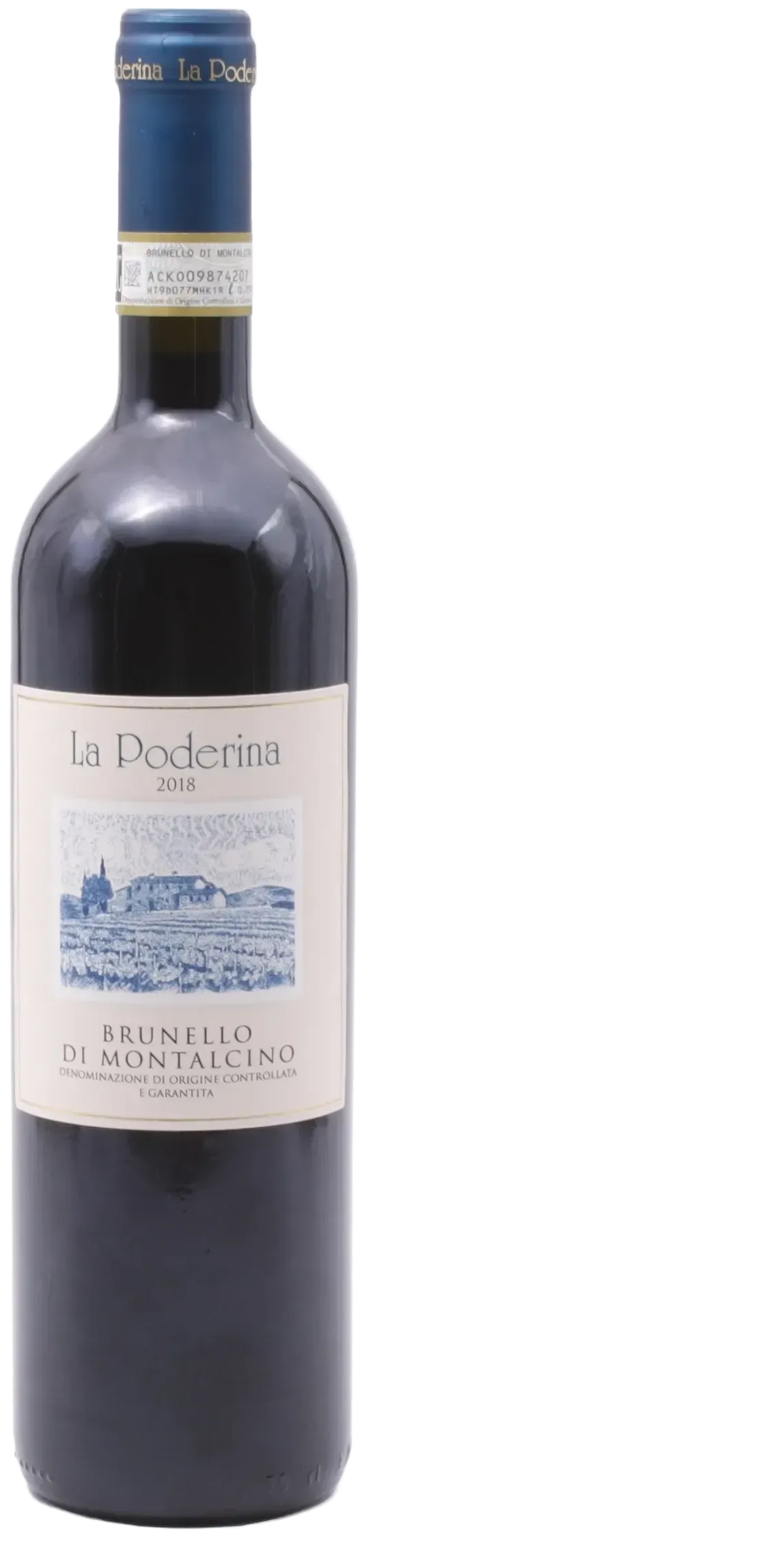
La Poderina Brunello di Montalcino DOCG 2018
29,90 €
la-cantina-italiana.de
ab 3,99 € Versandkosten
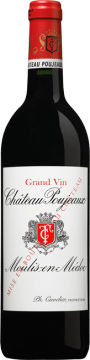
Chateau Poujeaux 2018
35,90 €
Vinatis
ab 6,00 € Versandkosten
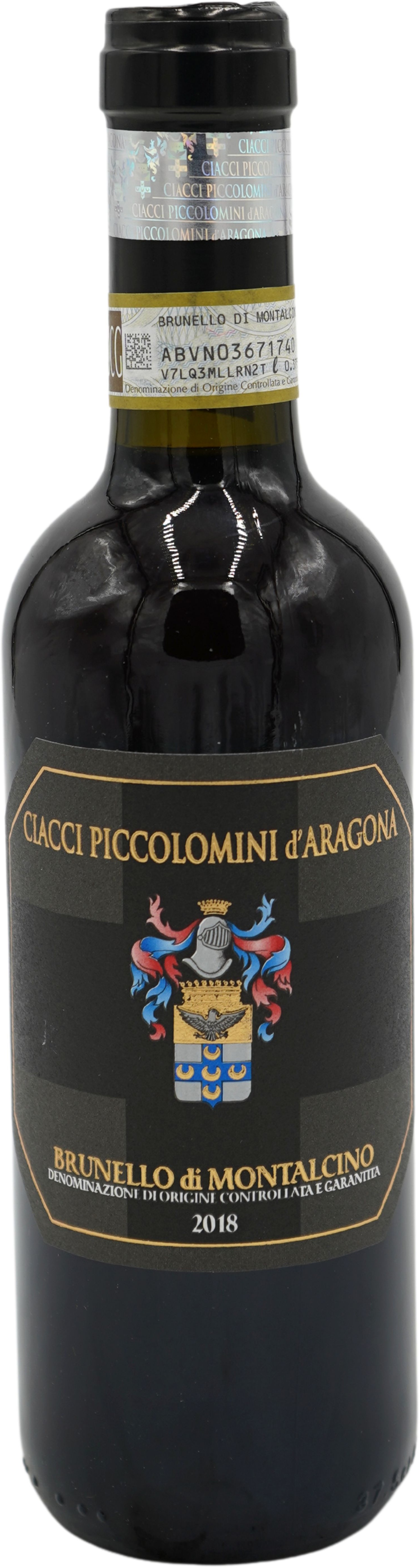
2018 Brunello di Montalcino - halbe Flasche
24,95 €
saittavini.com
ab 6,95 € Versandkosten

Weingut Kopp - Roter Porphyr Spätburgunder - 13% v...
16,90 €
time2taste.com
ab 6,95 € Versandkosten
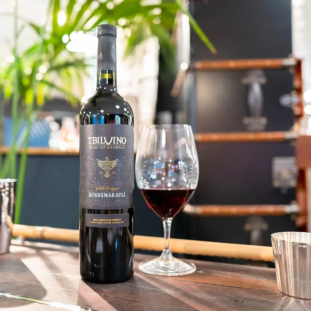
Tbilvino Kindzmarauli 2022 Rotwein 0,75 L medium s...
13,95 €
suhl-shop.de
ab 4,90 € Versandkosten
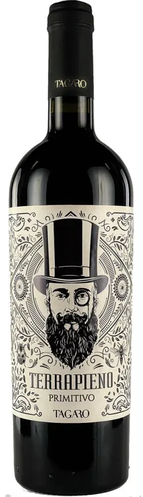
Tagaro - Primitivo IGP Terrapieno - 2022 | 6er Kar...
10,65 €
weinkost-shop.de
ab 8,60 € Versandkosten
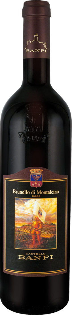
Castello Banfi Brunello di Montalcino DOCG
28,90 €
ebrosia Weinshop
ab 5,90 € Versandkosten
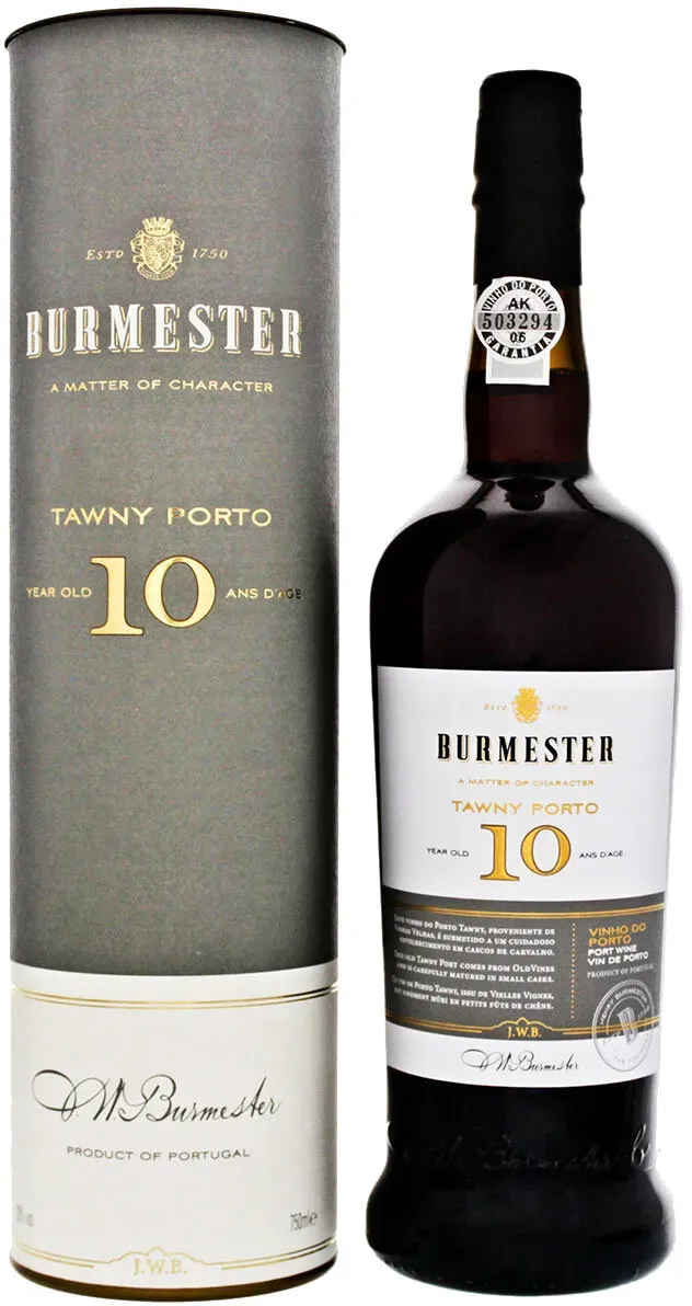
Burmester 10 Jahre Tawny Port
22,99 €
Whiskyfass
ab 5,88 € Versandkosten

Santa Cristina Rosso - 2022 - Antinori - Santa Cri...
7,90 €
weinfreunde.de
Versandkostenfrei
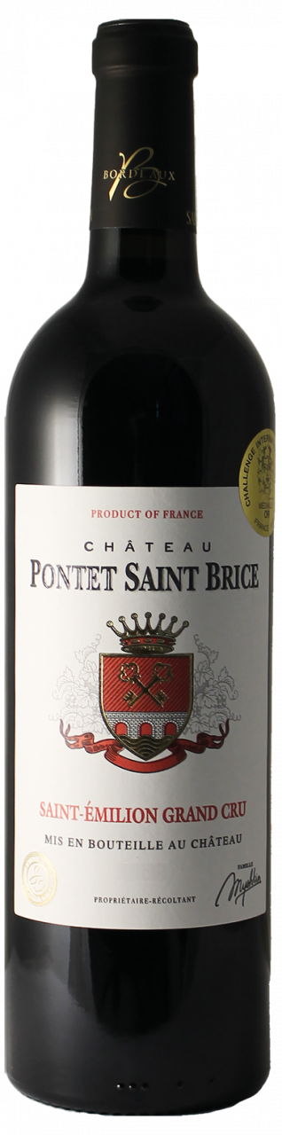
Château Pontet Saint Brice Saint-Émilion Grand Cru...
20,95 €
Brogsitter
ab 6,99 € Versandkosten

Steckparavent Weide
24,95 €
meingartenversand.de
ab 19,90 € Versandkosten
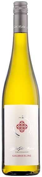
Tim Strasser Rothes Gut Meissen Goldriesling trock...
11,49 €
getraenkewelt.de
ab 7,90 € Versandkosten

Torre Santa Primitivo Puglia IGT 13,0 % vol 0,75 L...
3,66 €
netto-online.de
ab 5,95 € Versandkosten